WireWorld Computer Home Elements Gates Devices Modules Units Appliances  

WireWorld Computer

The Extended Devices

The devices rigorously extend the capabilities in WireWorld. They allow you to do more useful work, such as creating a crossing of two wires or a memory cell.

The clock device sends out regular signals without receiving any input.
The diode device allows electrons to pass in only one direction.
The crossing device is used for crossing the data on two wires.
The duplex device duplicates a signal.
The demultiplexer device controls which output wire the input data is sent to.
The multiplexer device controls which input wire the output data come from.
The latch device is a bistable circuit which can store a single bit of information.
The ROM device is a read-only memory.
The edge-detector device detects a positive or negative edge.
The divide-by-2 device divides the frequency of the input signal by 2.
 
The Clock Device
 

The clock device sends out regular signals without receiving any input.

The clock device

The top clock device ticks once every six generations. This is called a 6-cycle clock. The middle clock device ticks once every 24 generations and is called a 24-cycle clock. The bottom clock device contains the number 0110.1111 in 48 copper cells, hence a 48-cycle clock, and sends out this number.

The wire that comes up from the bottom left contains a start-of-data indicator for the output wire of the bottom clock device.

The Diode Device

The diode device allows electrons to pass in only one direction.

The diode device

The top diode device faces forward allowing the electron flow from left to right. The bottom diode device faces backward, stopping the flow of electrons.

The two 12-cycle clocks on the left serve to provide example information.

 
The Crossing Device
Truth table wire crossings

The crossing device is used for crossing the data on two wires.

The asynchronous crossing device

This asynchronous crossing device is designed by David Moore and Mark Owen.

It outputs (A, B) ⇒ (A ∧ B, B ∧ A). So it only works if signals come in at different times. If two signals come in at the same time, nothing will be forwarded.

The asynchronous crossing device will prove especially useful with the ROM device.

The full crossing device

This full crossing device outputs (A, B) ⇒ (B, A). So it works correctly with all four possible bit patterns 00, 01, 10 and 11. This full crossing device consists of three interconnected exclusive-or gates.

The special crossing device

This special crossing device outputs (A, B) ⇒ (A ∧ B, A). So the top input signal (A) is correctly transmitted to the bottom output wire (A). The top output wire contains however (A ∧ B) instead of B.

The special crossing device will prove especially useful with the multiplexer device.

The Duplex Device

The duplex device duplicates a signal.

The two and three duplex device

The top duplex device is a single hat shaped device which makes one duplicate of the input signal. The bottom duplex device contains a hat on top of the hat which makes two duplicates of the input signal. You can make more duplicates by locating more hats on top of the hats.

The four duplex device

This duplex device makes exactly four copies of the input signal.

 
The Demultiplexer Device
 

The demultiplexer device controls which output wire the input data is sent to.

The demultiplexer device

This is an externally controlled demultiplexer device (a switch) designed by Karl Scherer.

The input data is routed to the bottom output wire when the control line is active. Otherwise, it will be routed to the top output wire. To connect the input data to the top or the bottom output wire for a long time one can use a latch.

The wire that comes up half way from the bottom contains a start-of-data indicator for the output wire.

The Multiplexer Device

The multiplexer device controls which input wire the output data come from.

The multiplexer device

This externally controlled multiplexer device is designed by Karl Scherer.

The control signal connects the top or bottom input data to the output wire. The top input data is routed to the output wire when the control line is active. Otherwise the bottom input data will be routed to the output wire. A T-latch device is used to connect the top or bottom input data to the output wire for a long time.

Multiplexer device (junction) designed by Karl Scherer
 

Diagram multiplexer device

The Latch Device
The classic mono input T-latch device The classic mono input T-latch device

The latch device is a bistable circuit, a memeory cell, which can store a single bit of information. It has one of two states: set or reset, and it sends out a steady stream of electrons once it is set.

The SR-latch device

This dual input SR-latch (set-reset) device has seperate set and reset points. The SR-latch device is set with the top input wire and reset with the bottom input wire. It is possible to set the SR-latch device several times in a row before resetting it again. It is also possible to reset the SR-latch device several times in a row before setting it again. The state of the SR-latch device is stored in the small loop in the center. While the SR-latch device is set an eletron is continuously circling around.

The T-latch device

This mono input T-latch (toggle) device, designed by Ty Finally in 2022, has a single input for toggling between set and reset. It is not possible to set the T-latch device twice in succession, because the second attempt will always toggle the state of the T-latch device.

The latch device is similar to the flip-flop device. However, the flip-flop device includes a clock signal while the latch device does not.

The ROM Device

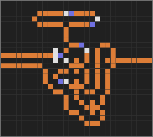
The ROM device is a read-only memory. It can only be adjusted through "hardware", by changing the copper cell arrangement.

The two rom gates

This ROM device, designed by David Moore and Mark Owen, consists of a grid of multiple linked rom gates. The rom gates are either and-not/or gates, visible on the left, or and-not/and-not gates, visible on the right. The outstretched arms and legs of the rom gates are to connect the rom gates together.

The ROM device

By selecting which input control wire is active you get different results. When the top input wire is active you get the output pattern 1011. When the bottom input wire is active you get the output pattern 0110. The 12-cycle clock on the bottom left indicates when the output data can be read.

The actually stored bits in the grid are those rom gates with an absent ear at the bottom left, the and-not/or gates. Each incoming electron moves through the rom gates to the bottom right. Whenever an electron encounters a rom gate with an absent ear, an and-not/or gate, it creates a twin which travels to the bottom left where it exits.

This sample of the ROM device has a grid of 2 x 4 rom gates, with two input control wires and four output data wires. However, if you want to display a decimal digit with a seven segment display, you will need 10 input control wires and 7 output data wires. This forms a grid with a total of 10 x 7 rom gates.
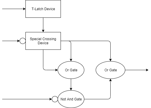
 
The Edge-Detector Device
 

The edge-detector device detects a positive or negative edge.

The positive edge detector device

This positive-edge-detector device forwards a signal when it detects the first binary 1, an electron, in a series of binary 1's.

The negative edge detector device

This negative-edge-detector device forwards a signal when it detects the first binary 0, a missing electron, after a series of binary 1's.

The Divide-By-2 Device

The divide-by-2 device divides the frequency of the input signal by 2.

The divide-by-2 device

This divide-by-2 device uses a T-latch device to remember the state it is in, 1 or 0. Next, a negative-edge-detector device is used to switch on the negative edge. A positive-edge-detector device could also be used here, to switch on the positive edge.

The output wire at the bottom indicates the original clock frequency.

 
Contact Me

This website contains my take on the marvelous WireWorld Computer
For questions, remarks or useful supplements (sorry, no javascript available)

Last update: September 2nd 2022

Camiel Wijffels
×
#